
Use Figure FA-33 according to the installation and power connection method


[1] [BLACK/WHITE] [When turning the lock; output [+] 12V power supply]
[2] [RED] [Original vehicle input [+] 12V power supply]
[3] [BLACK][input]
[4] [RED/BLACK][output]
*** [Connect the connector on the original car. if you find that the lock has not been connected to the power supply, please switch 1 and 2 to each other]
|
|
|
|
|||||||||||||||
|
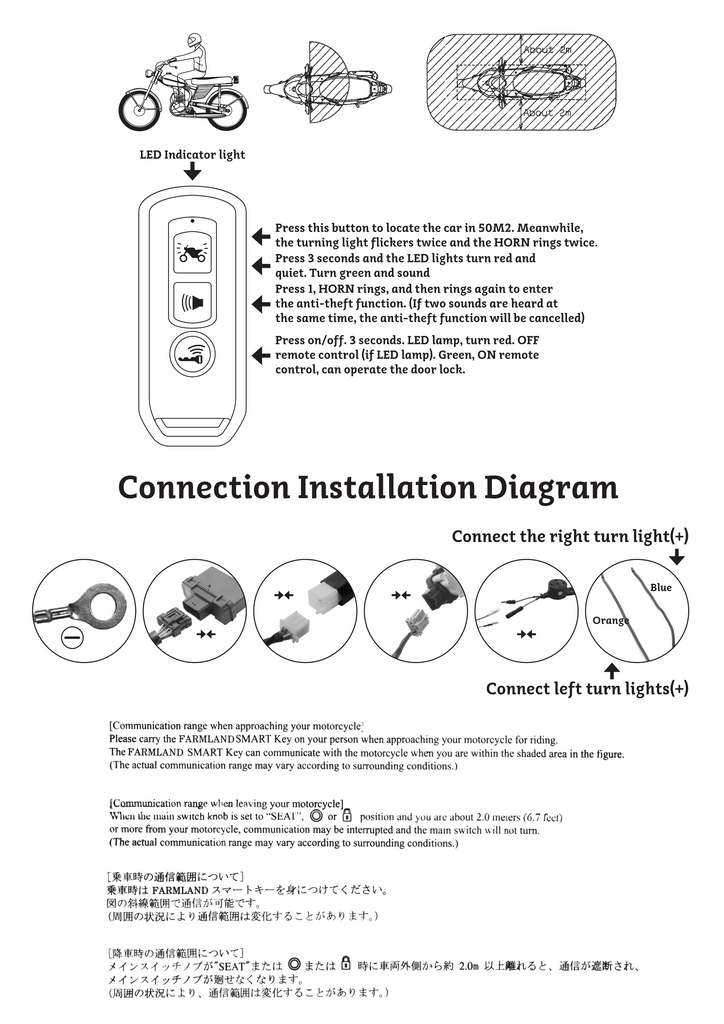
[Communication range when leaving your motorcycle], Wheu the main switch knob is set to (i)"SEAI", or position and you are about 2.0 merers (6.7 fcet)or more from your motorcycle,communication may be interrupted and the main switch will not turn.(The actual communication range may vary according to surrounding conditions.) |
|||||||||||||||||


